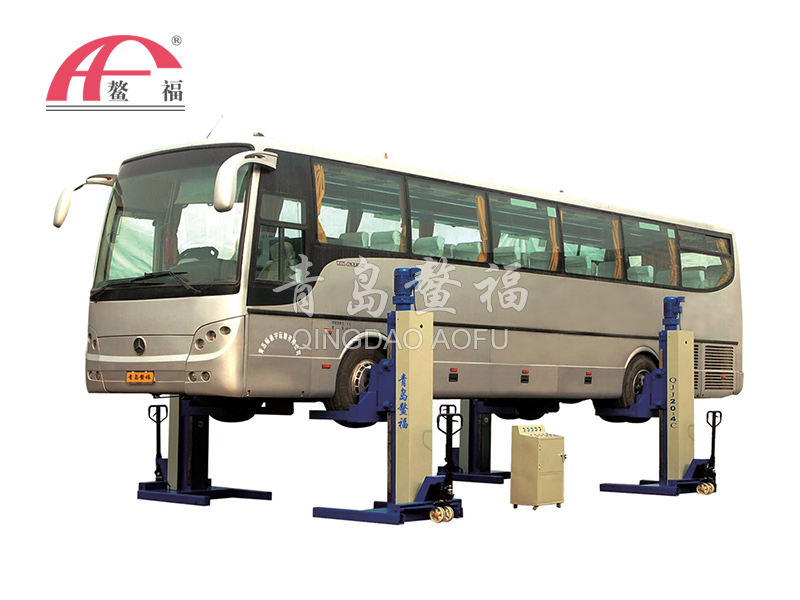
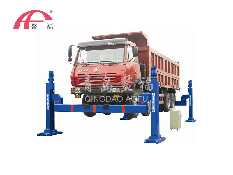
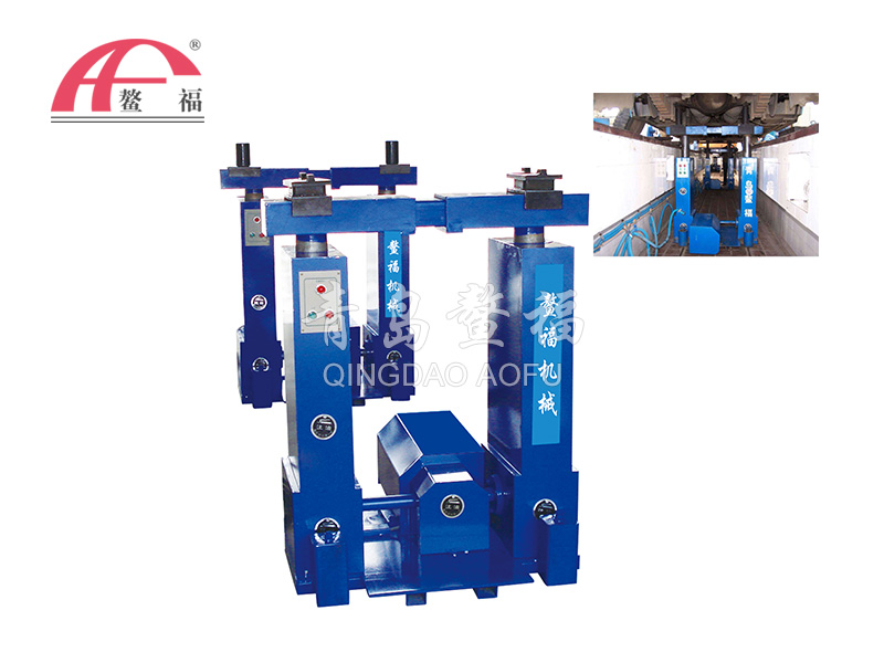
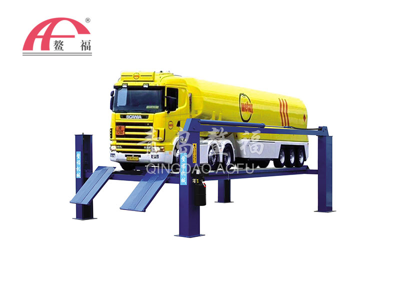
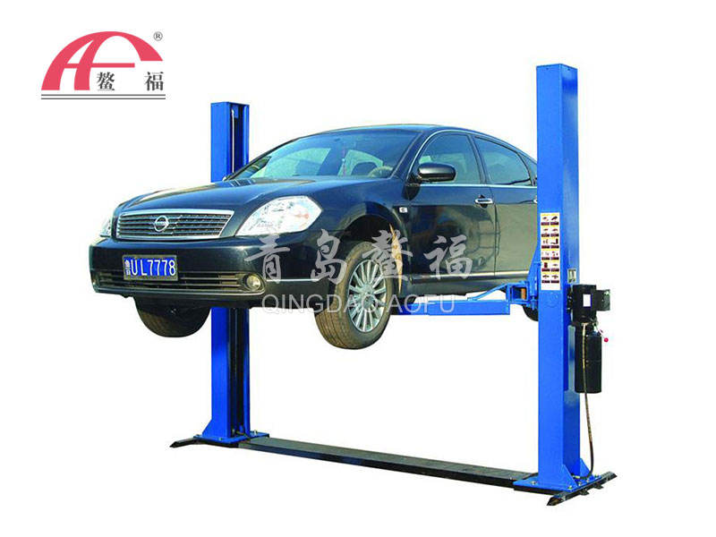
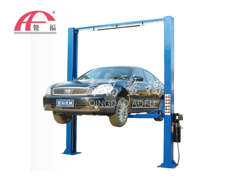
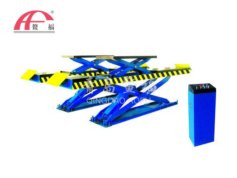
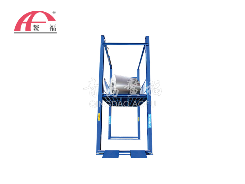
The speed control circuit is a circuit that controls the movement speed and speed switching of the actuator in the hydraulic system of the hydraulic lifting platform.
The main control methods are valve control, pump control and actuator control. Commonly used speed control loops are speed control loops, fast loops and speed switching loops.
The basic principle of the speed control loop The system often needs to adjust the movement speed of the hydraulic cylinder and the hydraulic motor to meet the needs of the main engine's working cycle. The speed of the hydraulic cylinder and hydraulic motor is determined by the displacement and the input flow. It can be seen that to control the speed of the cylinder and the motor, it can be achieved by changing the flow rate or by changing the displacement.

For the hydraulic cylinder in the hydraulic vehicle lifting platform, it is unrealistic to adjust the speed by changing its effective area A (equivalent to the displacement). Generally, the speed can only be adjusted by changing the flow rate. For variable displacement motors, speed regulation can change both flow and motor displacement.
Therefore, the speed control loop mainly has the following three ways:
1. Throttling speed control circuit: oil is supplied by a quantitative pump, and a flow valve is used to adjust the flow into or out of the actuator to achieve speed regulation;
2. The volume throttling speed control circuit uses a pressure-limiting variable pump to supply oil, and the flow valve regulates the flow into the actuator, and the flow of the variable pump is adapted to the regulating flow of the regulating valve to achieve speed regulation.
3. Volume speed control circuit: adjust the speed by adjusting the displacement of the variable pump or variable motor;
In addition, several quantitative pumps can be used in parallel, and one pump or several pumps can be started to supply oil to achieve graded speed regulation according to different speed requirements.

